AUTHOR
Benjamin Nelson, Engineer, Industry Expert
Electromagnetic Interference (EMI) is often called “static” or “interference.” It is an externally generated disturbance that can affect the performance of an electrical circuit. Remember when lines used to appear on television screens when a vacuum or blender was running at the same time? They were the result of EMI. EMI can also affect AM radio in particular, but can also impact FM radio, cellular, and other communication devices such as remote controls, emergency call devices, TVs, sometimes even hearing aids.
LED lighting does not generate EMI. The EMI is generated by the electronic drivers that are powering the LED. The adoption of these drivers replaces the electromagnetic ballasts which operate at a much lower frequency (60Hz). Electronic drivers operate at 20-60 kHz, which is between 50-200 times the frequency of a magnetic ballast, producing much higher levels of EMI due to the high speed switching. The tradeoff is that the higher frequency drivers are much smaller, lighter, quieter and more efficient.
Unfortunately, there is very little regulation with regard to EMI in the lighting industry and as a result, lighting manufacturers are simply designing to the FCC specification using ferrite beads and various shielding techniques. This technique is enough to satisfy FCC specification part 15, which is sufficient for laboratory conditions, but is inadequate for the application of Street Lighting.
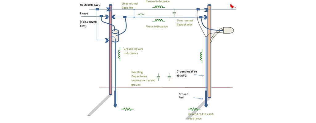
This was exactly the case when the city of Amarillo, Texas piloted the installation of a set of LED streetlights. A “concerned citizen” reported that there was significant AM radio interference after the LED lights were installed. After an exhaustive analysis, it was determined that the luminaire was the source of the problem. A small amount of RF noise can couple on to the power or ground line, which then serves as a radiating antenna. The length of the power line coupling the noise controls which frequencies radiate well. Since there are many different line lengths, the effects could be different for each house in the same neighborhood. There is also the potential for this interference (noise) to be induced back to the luminaire through wire routing, amplified by the resonances in the power circuitry or lack of a dedicated ground lead.

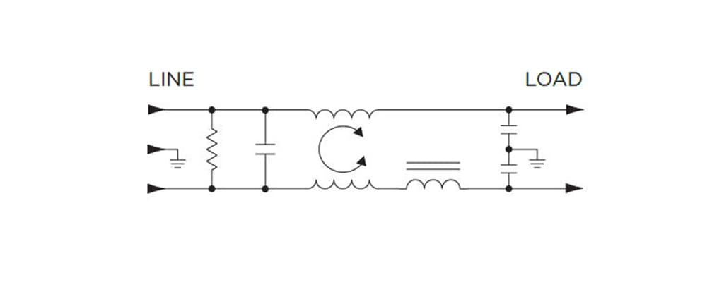
So how do we stop these sources of noise from interfering with our other devices? We stop them at the source before they are allowed to cause problems. EMI filters are designed to filter out troublesome high frequency by using a low pass, or L-C filter. These filters are normally made up of passive components such as inductors (L) and capacitors (C). The inductor allows for low frequency or DC currents to pass through, while blocking high frequency current. The capacitor provides a low impedance path to divert the high frequency noise away from the input of the filter, and either back into the power supply, or into the ground connection. In the schematic below, the resistors are used to help dissipate the “filtered” load, effectively capturing the noise before it is able to couple with other parts of the system.

In addition to assisting to meet EMI regulations, the filter also has to meet safety standards. The inductor temperature rise is measured for mains operation, and the minimum electrical spacing between line, neutral and ground are controlled. This reduces the risk of fire and electrical shock. The capacitors are also individually safety certified, depending on their position in the circuit. Special “X” capacitors are used across the input terminals to prevent a short circuit and possible fire hazard. “Y” capacitors are connected from the AC circuit to ground, and prevent the possibility of electrical shocks.
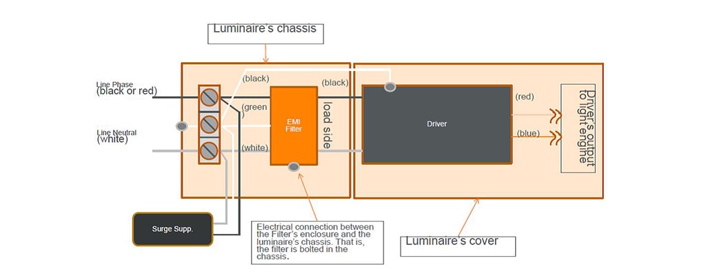
The FB series of EMI filters from TE provides the ideal solution for such street lighting issues. This series is approved at 277VAC, which fits in to most lighting applications. TE has also obtained UL recognition, along with a UL listing. The FB series also supports the use of solid copper leads, which is preferred by the lighting industry. Nearly all EMI filters are approved to only 250VAC, which make the TE product an immediate solution to lighting customers. As shown below, the EMI filter should be placed as close to ballast or driver as possible to eliminate RF from traveling down the conductors and acting like a transmitting antenna.

Although the addition of an EMI filter does add cost to the overall design, it does avoid potential complaints from residents or other users of street lighting that experience interference due to EMI. The upfront protection will avoid a complex and costly analysis of source of the interference. The FCC spec states that: “Parties responsible for equipment compliance should note that the limits specified in this Part will not prevent harmful interference under all circumstances.” (FCC part 15, Section 15.15, paragraph c).
This statement states that a luminaire may pass under lab conditions, but may not when surrounded by distribution equipment, substations, and transmission lines among other potential sources of interference.
About the Author
More Content by TE Connectivity


